VESA協會定義了DisplayPort(DP) 與 USB Type-c之間的關聯。透過DP alternate mode (SID=0xFF01)可以將某些Type-C的腳位修改為Displayport的訊號傳輸
這份spec主要定義3種USB Type-C與DisplayPort可能出現的3種產品模式:
- USB Full-Featured Type-C cable assembly
- USB Type-C plug to DP/mDP cable assembly
- USB Type-C plug to another video interface (e.g. HDMI, VDVI, or VGA) cable assembly (i.e., with a plug) or adapter (i.e., with a receptacle)
整份spec.都圍繞在這3類產品的介紹

考量產品可能包含DP connector, 首先必須考慮BR(bit rate)。
規格書中定義DP_BR代表DP spec. V1.3中的其中一種傳輸速率(one of RBR, HBR, HBR2, and HBR3)
- 810MHz for 8.1Gbps/lane (high bit rate 3, HBR3)
- 540MHz for 5.4Gbps/lane (high bit rate 2, HBR2)
- 270MHz for 2.7Gbps/lane (high bit rate, HBR)
- 162MHz for 1.62Gbps/lane (low bit rate, RBR)
另外定義GEN2_BR代表USB r3.1 Gen2傳輸速率
- up to 10Gbps
Table 2-1 定義第一種產品模式。因為Host和Monitor都是Type-C,中間必須透過Type-C Cable連接( Type-C Cable在USB Type-C spec.中有詳細定義)
針對BR以及lane數,分成4種pin assignment

- Adapters (USB Type-C Plug at one end and DisplayPort plug at the other end) shall always use DP_BR.
- USB Type-C Protocol Converters (USB Type-C plug on one end and non-DisplayPort video connector at the other end) shall support DP_BR, but may also support GEN2_BR.
- Pin assignment A, B 是以GEN2_BR傳輸,所以Gen1 passive cable (5Gbps)無法支援
- Gen2 Active cable只能使用Pin assignment A, B
3. Pin assignment
為了分辨腳色,規格書定義DFP_D為DP source, 提供DP訊號例如電腦
UFP_D為DP sink, 接收DP訊號例如螢幕
Table3-1 & 3-2 定義了DFP_D用到的pin assignment

為了分辨腳色,規格書定義DFP_D為DP source, 提供DP訊號例如電腦
UFP_D為DP sink, 接收DP訊號例如螢幕
Table3-1 & 3-2 定義了DFP_D用到的pin assignment


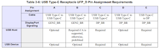
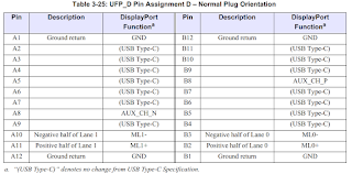
Table 3-3 & 3-4 定義了UFP_D用到的pin assignment, 分別對應DFP_D腳位


- Pin Assignments A, B, C, and D are intended for use in conjunction with USB Type-C to USB Type-C Cables and with adapters from USB Type-C to other video standards. Pin Assignment E is intended for use in conjunction with adapters from USB Type-C to DP plugs or receptacles.
- DP protocol is carried using GEN2_BR when using Pin Assignments A and B. DP protocol is carried using DP_BR when using Pin Assignments C, D, and E.
- Pin Assignments B and D are used as variants of Pin Assignments A and C, respectively, to simultaneously carry one channel of USB Enhanced SuperSpeed protocol with one or two DP lanes. This configuration is described as Multi-function.
- Pin Assignment E allows the USB Type-C connector flip to be implemented by DFP_Ds that support pin allocation reversals (i.e., ML0, ML1, ML2, and ML3 can be reversed to ML3, ML2, ML1, and ML0, respectively)
Table 3-5 & 3-6 定義USB Type-C Receptacle端 DFP_D和UFP_D必須支援的pin assignment
(pin assignment C & E)

(pin assignment C & E)


Table 3-7 & 3-8 定義USB Type-C Plug端 DFP_D & UFP_D必須支援的pin assignment


- Systems supporting a DFP_D on a USB Type-C receptacle shall support HBR.
- Adapters and captive cable docks supporting a DFP_D on a USB Type-C Plug and adapting this to a DisplayPort connector shall be capable of supporting four DP lanes.
- Adapters and captive cable docks supporting a DFP_D on a USB Type-C Plug and adapting this to a non-DP video interface may support two or four DP lanes, according to adapter functionality.
---------------------------------------------------------------------------------------------------------
以下為各種pin assignment的詳細介紹
※ 若同時支援DisplayPort 和 USB 3.1訊號,即為spec.定義的Multi-function Systems
以下為各種pin assignment的詳細介紹
※ 若同時支援DisplayPort 和 USB 3.1訊號,即為spec.定義的Multi-function Systems
⑴. Pin Assignment A


This pin assignment is appropriate only for USB Type-C to USB Type-C cables and UFP_Ds with
USB Type-C plugs. It supports passive and active USB Type-C to USB Type-C Gen 2 cables, as
follows:
⑵. Pin Assignment B


This pin assignment is appropriate only for USB Type-C to USB Type-C cables and UFP_Ds with
USB Type-C plugs. It supports passive and active USB Type-C to USB Type-C Gen 2 cables, as
follows:
⑶. Pin Assignment C
DisplayPort electrical signaling for this pin assignment shall comply with DP Standard for transmission rates up to RBR, HBR, HBR2, or HBR3, as supported by the system.


⑷. Pin Assignment D
DisplayPort electrical signaling for this pin assignment shall comply with DP Standard for transmission rates up to RBR, HBR, HBR2, or HBR3, as supported by the system.


⑸. Pin Assignment E
DisplayPort electrical signaling for this pin assignment shall comply with DP Standard for transmission rates up to RBR, HBR, HBR2, or HBR3, as supported by the system, except that the reference cable model shall be for the USB Type-C to DP cable defined in Section 4.2.3.

※ USB Gen 2 PHY Layer Signaling for DisplayPort (GEN2_BR)
目前規格書沒有定義DP使用的GEN2_BR PHY, 但未來可能在DP spec.新增;若定義上有衝突,以DP spec優先
3-1 AUX Signaling
AUX shall be supported on the USB Type-C connector when operating in DisplayPort Mode using
differential 100Ω-terminated signaling on the receptacle pin A8 and B8 connection. AC-coupling
capacitors shall be placed between the AUX_CH_P/AUX_CH_N transceiver and USB Type-C
Receptacle.
Note. Receptacle pins A8 and B8 are disconnected in the system until the connection is
switched into DisplayPort Mode and a configuration is selected. Likewise, plug
pins A8 and B8 on adapter cables are disconnected until the connection is switched
into DisplayPort Mode and a configuration is selected.
Figure3-1 使用USB Type-C to Type-C cable連接DFP_D和USP_D
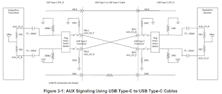

Figure3-2 為Type-C(DFP_D) to DP(UFP_D) adapter示意圖
Figure3-3 為DP(DFP_D) to Type-C(UFP_D) adapter示意圖


Figure 3-4 illustrates the system design of a DFP_D on a USB Type-C connector connected to a
Protocol Converter. In this design, the Protocol Converter is used to convert DP protocol to a non-
DP audio-video protocol.

3-2 HPD Signaling
HPD shall be supported on the USB Type-C connector when operating in DisplayPort Mode
by way of USB PD messages that carry DisplayPort Status information

Two DisplayPort Status flags are defined to communicate HPD state:
◾ DFU_U可以透過傳遞DP Status Update command,告知目前DP狀態
UFP_U可以透過回應DP Status Update command, 或是傳遞DisplayPort Attention command,告知目前DP狀態
◾ A USB Type-C to DP adapter shall implement a converter able to convert between the HPD signal
and PD messages in either direction.
◾ A USB Type-C to non-DP audio-video Protocol Converter may implement the PD-to-HPD
converter (as described in this section) or directly process the DisplayPort Status updates.
◾ On first connection, HPD shall be assumed low.
HPD-to-PD converter
◾ An HPD-to-PD converter that receives a DP HPD signal through an external connector shall implement the HPD de-bounce recommendation and glitch filtering provided in DP Standard, Section 3.3, on its HPD detector. The HPD-to-PD converter shall not indicate HPD_High in a DisplayPort Status message during the time that HPD is being de-bounced (i.e., it indicates HPD_High only after de-bouncing has been applied and was completed by HPD being detected high for 100ms).
◾ When DisplayPort Mode has not been enabled, an HPD-to-PD converter shall not transmit any Status update messages. When DisplayPort Mode is enabled, the HPD-to-PD converter shall transmit the current HPD state as part of the initial DisplayPort Status Update message exchange.
PD-to-HPD converter
◾ A PD-to-HPD converter shall drive a low level on its HPD driver at all times that DisplayPort
Configuration on the USB Type-C interface is not enabled. The PD-to-HPD converter shall only
indicate HPD’s current state after the SBU isolation switches have been closed to connect the AUX
channel.
3-2-1 HPD Schematics
Figure 3-6 illustrates the schematic for an implementation of an HPD-to-PD converter in a UFP_D and a PD-to-HPD converter in a DFP_D and their connection using a USB Type-C to USB Type-C Cable assembly.

Figure 3-7 illustrates the schematic for an implementation of a PD-to-HPD converter in a DFP_D
and an HPD-to-PD converter in a USB Type-C to DP adapter and its connection to a UFP_D on the
DisplayPort connector. Because the USB Type-C to DP adapter is reversible, the HPD transmitter in the HPD-to-PD converter is disabled when signaling is transmitted in this direction.
Figure 3-8 illustrates the schematic in reversible direction.


Figure 3-9 illustrates the schematic for an implementation of a PD-to-HPD converter in a DFP_D
and an HPD-to-PD converter in a Protocol Converter. In this design, the Protocol Converter is used
to convert DP protocol to a non-DP audio-video protocol.

3-3 DisplayPort Connector CONFIG1 and CONFIG2 Pins
The DP plug’s CONFIG1 and CONFIG2 pins in USB Type-C to DP adapters shall each be pulled
low to GND with a 1MΩ pull-down resistor.
延伸閱讀: DP alternate mode on USB Type-C Standard (二)
Reference:
1. VESA DisplayPort Alt Mode on USB Type-C Standard (DisplayPort Alt Mode), Version 1.0b, Draft
2. VESA - DisplayPortTM Alternate Mode on USB-CTM - Technical Overview


This pin assignment is appropriate only for USB Type-C to USB Type-C cables and UFP_Ds with
USB Type-C plugs. It supports passive and active USB Type-C to USB Type-C Gen 2 cables, as
follows:
- Four DP lanes for passive Gen 2 cables
- Two DP lanes for active Gen 2 cables


This pin assignment is appropriate only for USB Type-C to USB Type-C cables and UFP_Ds with
USB Type-C plugs. It supports passive and active USB Type-C to USB Type-C Gen 2 cables, as
follows:
- Two DP lanes for passive Gen 2 cables
- One DP lane for active Gen 2 cables
⑶. Pin Assignment C
DisplayPort electrical signaling for this pin assignment shall comply with DP Standard for transmission rates up to RBR, HBR, HBR2, or HBR3, as supported by the system.
- This pin assignment is appropriate only for passive USB Type-C to USB Type-C cables and UFP_Ds / DFP_Ds with USB Type-C plugs.


⑷. Pin Assignment D
DisplayPort electrical signaling for this pin assignment shall comply with DP Standard for transmission rates up to RBR, HBR, HBR2, or HBR3, as supported by the system.
- This pin assignment is appropriate only for passive USB Type-C to USB Type-C cables and UFP_Ds / DFP_Ds with USB Type-C plugs.


⑸. Pin Assignment E
DisplayPort electrical signaling for this pin assignment shall comply with DP Standard for transmission rates up to RBR, HBR, HBR2, or HBR3, as supported by the system, except that the reference cable model shall be for the USB Type-C to DP cable defined in Section 4.2.3.
- This pin assignment is appropriate only for receptacles that accept plugs on DisplayPort to USB Type-C cables and for plugs on such cables. It supports passive and active cables.


※ USB Gen 2 PHY Layer Signaling for DisplayPort (GEN2_BR)
目前規格書沒有定義DP使用的GEN2_BR PHY, 但未來可能在DP spec.新增;若定義上有衝突,以DP spec優先
3-1 AUX Signaling
AUX shall be supported on the USB Type-C connector when operating in DisplayPort Mode using
differential 100Ω-terminated signaling on the receptacle pin A8 and B8 connection. AC-coupling
capacitors shall be placed between the AUX_CH_P/AUX_CH_N transceiver and USB Type-C
Receptacle.
Note. Receptacle pins A8 and B8 are disconnected in the system until the connection is
switched into DisplayPort Mode and a configuration is selected. Likewise, plug
pins A8 and B8 on adapter cables are disconnected until the connection is switched
into DisplayPort Mode and a configuration is selected.
Figure3-1 使用USB Type-C to Type-C cable連接DFP_D和USP_D

- The 2MΩ pull-down resistors on SBU1 and SBU2 are representative of the leakage of ESD and EMI/RFI components including termination to ensure that there are no floating nodes, and are intended to show compliance with zSBUTermination in USB Type-C Specification.

Figure3-2 為Type-C(DFP_D) to DP(UFP_D) adapter示意圖
Figure3-3 為DP(DFP_D) to Type-C(UFP_D) adapter示意圖


- The 3.3V levels in the adapters are derived from VCONN because not all DP UFP_D devices provide DP_PWR.
- The 470kΩ resistor represents a compromise between providing an adequate pull-down resistor to overcome these losses and the need for a relatively low threshold for the connection detection that this requires.
- The very weak (4.7MΩ) resistor on AUX_CH_N represents circuitry required to avoid a floating conductor when the adapter is not connected to a DP UFP_D without compromising the threshold in the DP UFP_D used to detect the adapter’s pull-up resistor.
Figure 3-4 illustrates the system design of a DFP_D on a USB Type-C connector connected to a
Protocol Converter. In this design, the Protocol Converter is used to convert DP protocol to a non-
DP audio-video protocol.

3-2 HPD Signaling
HPD shall be supported on the USB Type-C connector when operating in DisplayPort Mode
by way of USB PD messages that carry DisplayPort Status information

Two DisplayPort Status flags are defined to communicate HPD state:
- HPD_State – Indicates whether HPD’s logical state is high or low (denoted as HPD_Highor HPD_Low, respectively).
- IRQ_HPD – Indicates an IRQ_HPD (i.e., a high-to-low transition on HPD followed by a low-to-high transition was detected between 250us and 2ms later, as specified in DP Standard).
◾ DFU_U可以透過傳遞DP Status Update command,告知目前DP狀態
UFP_U可以透過回應DP Status Update command, 或是傳遞DisplayPort Attention command,告知目前DP狀態
◾ A USB Type-C to DP adapter shall implement a converter able to convert between the HPD signal
and PD messages in either direction.
◾ A USB Type-C to non-DP audio-video Protocol Converter may implement the PD-to-HPD
converter (as described in this section) or directly process the DisplayPort Status updates.
◾ On first connection, HPD shall be assumed low.
HPD-to-PD converter
◾ An HPD-to-PD converter that receives a DP HPD signal through an external connector shall implement the HPD de-bounce recommendation and glitch filtering provided in DP Standard, Section 3.3, on its HPD detector. The HPD-to-PD converter shall not indicate HPD_High in a DisplayPort Status message during the time that HPD is being de-bounced (i.e., it indicates HPD_High only after de-bouncing has been applied and was completed by HPD being detected high for 100ms).
◾ When DisplayPort Mode has not been enabled, an HPD-to-PD converter shall not transmit any Status update messages. When DisplayPort Mode is enabled, the HPD-to-PD converter shall transmit the current HPD state as part of the initial DisplayPort Status Update message exchange.
PD-to-HPD converter
◾ A PD-to-HPD converter shall drive a low level on its HPD driver at all times that DisplayPort
Configuration on the USB Type-C interface is not enabled. The PD-to-HPD converter shall only
indicate HPD’s current state after the SBU isolation switches have been closed to connect the AUX
channel.
3-2-1 HPD Schematics
Figure 3-6 illustrates the schematic for an implementation of an HPD-to-PD converter in a UFP_D and a PD-to-HPD converter in a DFP_D and their connection using a USB Type-C to USB Type-C Cable assembly.

Figure 3-7 illustrates the schematic for an implementation of a PD-to-HPD converter in a DFP_D
and an HPD-to-PD converter in a USB Type-C to DP adapter and its connection to a UFP_D on the
DisplayPort connector. Because the USB Type-C to DP adapter is reversible, the HPD transmitter in the HPD-to-PD converter is disabled when signaling is transmitted in this direction.
Figure 3-8 illustrates the schematic in reversible direction.


and an HPD-to-PD converter in a Protocol Converter. In this design, the Protocol Converter is used
to convert DP protocol to a non-DP audio-video protocol.

3-3 DisplayPort Connector CONFIG1 and CONFIG2 Pins
The DP plug’s CONFIG1 and CONFIG2 pins in USB Type-C to DP adapters shall each be pulled
low to GND with a 1MΩ pull-down resistor.
延伸閱讀: DP alternate mode on USB Type-C Standard (二)
Reference:
1. VESA DisplayPort Alt Mode on USB Type-C Standard (DisplayPort Alt Mode), Version 1.0b, Draft
2. VESA - DisplayPortTM Alternate Mode on USB-CTM - Technical Overview